
I attended a design development meeting in June of 2017 for a new development in Brighton, MA. The developer was building a new Mikvah building on the site, then tearing down the old Mikvah building, building a new synagogue where the old Mikvah stood, tearing down the old synagogue and then building a new apartment building where the old synagogue stood.
My question was “ What’s a Mikvah?”
In Judaism, a Mikvah is a pool of natural water in which one bathes for the restoration of ritual purity.
Situation – A Two story wood structure with open pools of water on the first floor.
The Mikvah building was to be a two-story wood structure with three open pools of water on the first floor and living quarters on the second floor.
Challenge
Having open pools of water in any building presents a challenge in designing the above grade vertical building enclosure assemblies. But wood-framed buildings present the biggest challenge. The fact is, they have a much greater food source for mold ( wood and paper ) than steel and concrete framed structures. Combined with the high humidity levels in the building due to the open pools of water in the building, the potential to grow mold is much greater for wood-framed buildings than steel, concrete or CMU framed buildings. Also, wood has the ability to absorb and store moisture. If the moisture levels in the wood exceed a certain amount by volume the wood will rot.
Control Interior Humidity Levels
The first step is to get the interior humidity levels under control. The HVAC Engineer on the project was tasked with this. He designed a dehumidification system to keep the interior RH at 55%. Now that we had this information, we could look into the design of the building enclosure assemblies.
Designing the Building Enclosure Assemblies for the Mikvah
Above Grade Exterior Walls
We started with the above grade exterior walls.
The original exterior wall design is shown in Figures 1 & 2.
In a normal wood-framed house that is not humidified this assembly will work.
With a wood framed building with 55% interior relative humidity, it will not.

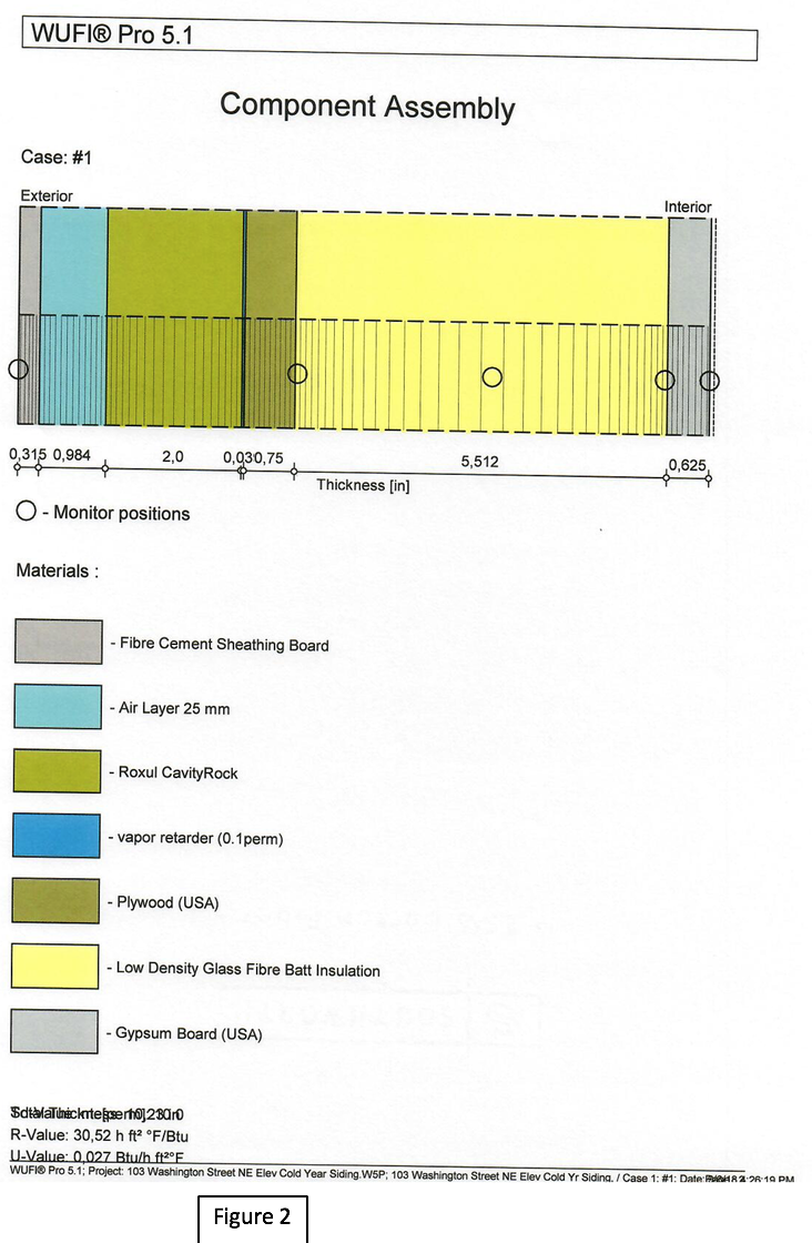
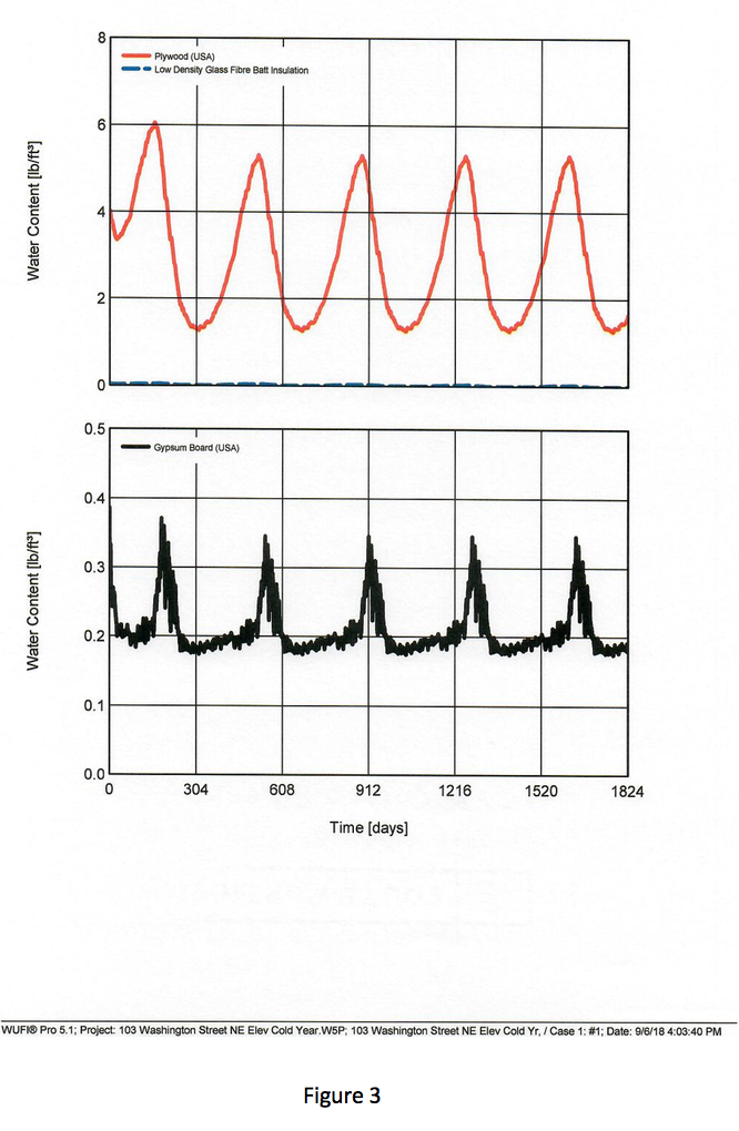
Figure 3 is an output from the WUFI® Pro 5.1 hygrothermal modeling program for the assembly in Figure 1. In running the program, I started the RH level across the assembly at 80% to simulate the moisture content of the components at the completion of construction. At this starting point, the moisture content of the exterior sheathing was 4 lbs/cf. Over the 5 years we ran the analysis, the moisture content rose well above this level every winter for an extended period of time.
I consider this a failure of the assembly.
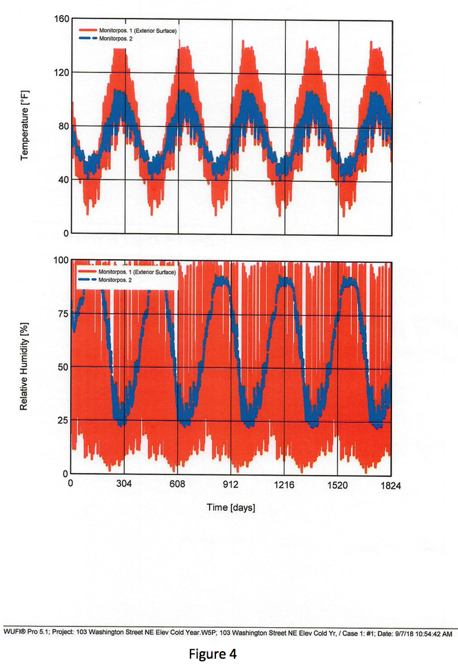
Furthermore, Figure 4 shows that the relative humidity at the interior face of the exterior sheathing ( Monitor Position 2 ) rose up to 95% for extended periods of time during the winter months.
This is also a failure of the assembly.
Figure 5 shows the results of the moisture content of the exterior sheathing of the assembly in Figure 2.
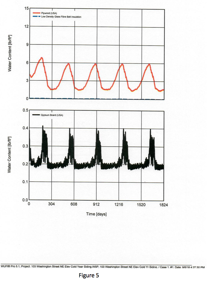
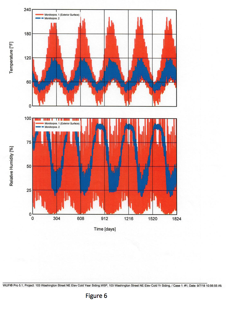
Figure 6 shows the relative humidity levels at the interior face of the exterior sheathing of the assembly in Figure 2.
This assembly experienced the same failure criteria as the assembly in Figure 1.
The solution for Managing Moisture Content
The answer is to move all of the insulation to the exterior of the exterior sheathing and change the insulation to spray polyurethane foam. This eliminates the temperature differential within the insulation that was in the stud cavity due to the insulation being in the studs. The change to spray polyurethane foam gave us one product in one plane installed by one contractor to give us the four barriers needed to effectively separate the interior environment from the exterior environment.
These barriers are Heat Barrier, Air Barrier, Water Barrier, and Vapor Barrier.
Building Must Meet the Massachusetts Stretch Energy Code
The developer wanted the building to meet the Massachusetts Stretch Energy Code. We calculated that we would need an above grade exterior wall assembly with an R-Value of about 24 in order to meet the code. In order to meet this requirement, we increased the thickness of the spray polyurethane foam insulation to 3” giving us an R-Value of 20.1. This was the least costly method to achieve this goal. We looked at putting an air, water and vapor barrier on the exterior sheathing and extruded polystyrene insulation over the air, water, and vapor barrier, but we would have had to increase the thickness of the extruded polystyrene to 4” to match the R-Value of the spray polyurethane foam. But it was more costly than the spray polyurethane foam. And we would have had to increase the wall thickness to accommodate it, adding further costs to the project.
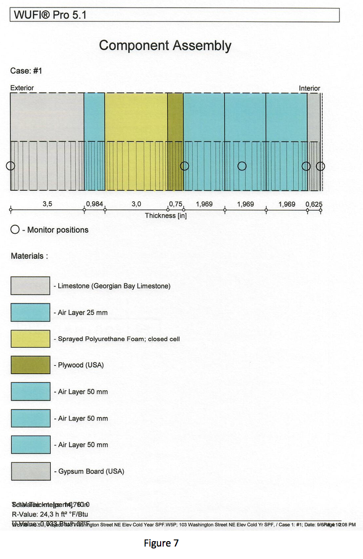
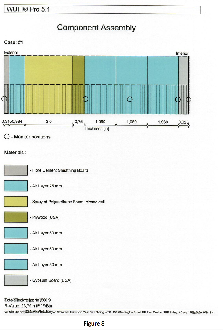
Figures 7 and 8 show the revised exterior wall assemblies. The R-Value of these assemblies is calculated by WUFI® and are shown in the bottom left-hand corner of the Figures. The energy consumption of the building was calculated and the design of the building met the Stretch Code.
Moisture Content
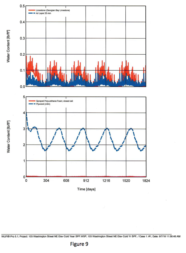
Figure 9 shows the moisture content of the exterior sheathing in the assembly in Figure 7. The exterior sheathing dries from the 80% RH moisture content levels and stays well below it.
Acceptable Relative Humidity Levels
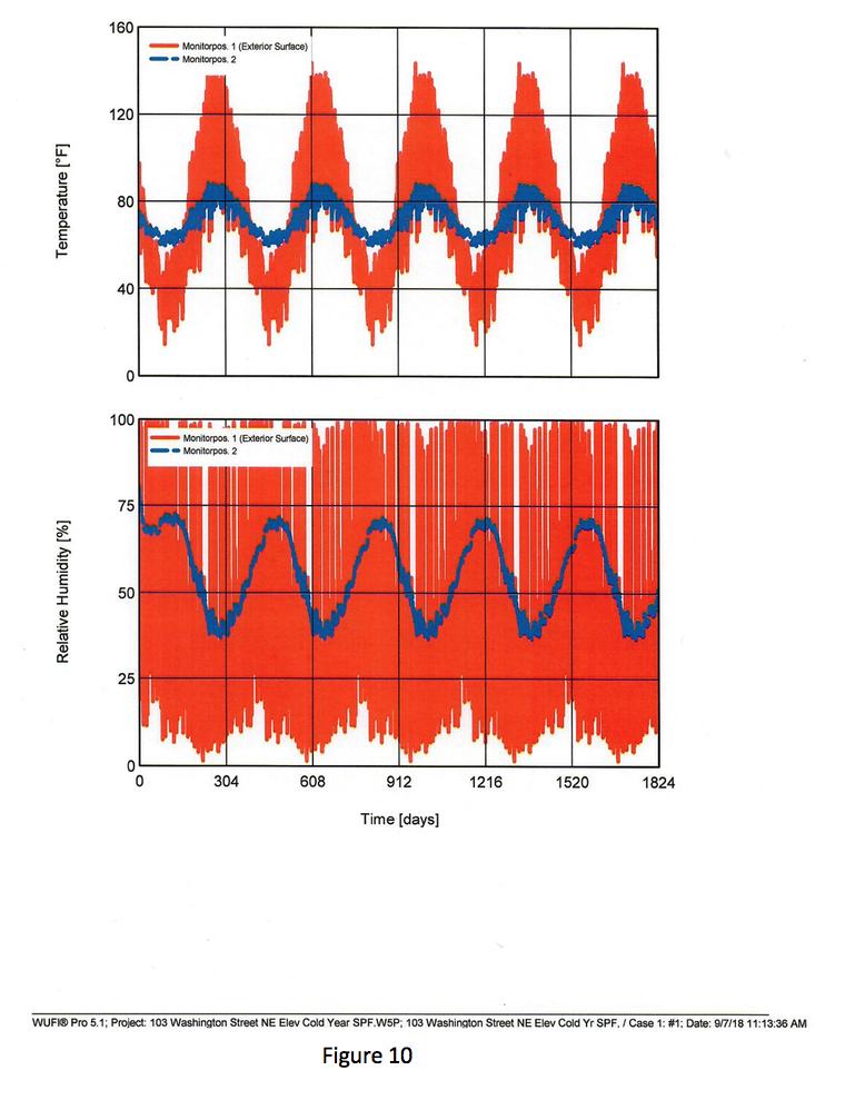
Figure 10 shows the relative humidity levels at the interior face of the exterior sheathing. This peaks at 70% during the Winter.
This assembly is acceptable.
Moisture Content of the Exterior Sheathing
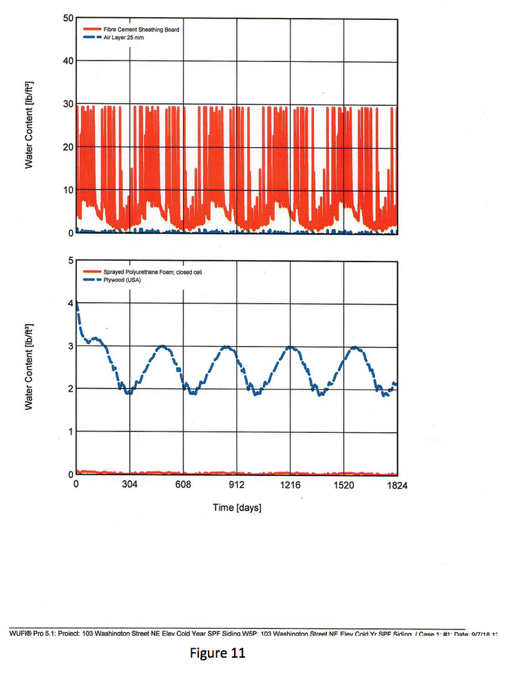
Figure 11 shows the moisture content of the exterior sheathing in the assembly in Figure 8. The exterior sheathing dries from the 80% RH moisture content levels and stays well below it.
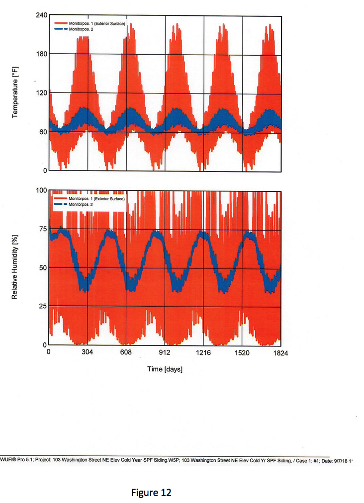
Acceptable Relative Humidity Levels During Winter
Figure 12 shows the relative humidity levels at the interior face of the exterior sheathing. This peaks at 75% during the Winter. This assembly is also acceptable.
So we are done, right? Nope. We have another issue to deal with.
Another Challenge –The metal Z-furring Creates a Thermal Bridge
The siding is attached to vertical metal Z-furring members that are attached to the wood-framed back-up wall. The metal Z-furring creates a thermal bridge through the insulation. This does not comply with the continuous insulation requirements in the 2015 International Energy Code ( IEC ). This code defines continuous insulation as that which only has fasteners extending through it. Functionally, the Z-furring, in being a thermal bridge, will lose heat to the exterior of the building during the Winter months thus dropping the temperature of the exterior sheathing where it is in contact with the Z-furring to the point where it can cool the air in the stud cavity that comes into contact with these locations below its dew point temperature resulting in condensation forming on the interior face of the exterior sheathing at these locations. It also reduces the effectiveness of the insulation layer. At 16” O.C. vertically, the effectiveness of the insulation in stopping radiant heat transfer through the building enclosure assembly is reduced by more than 50% due to the thermal bridging created by the Z-furring.
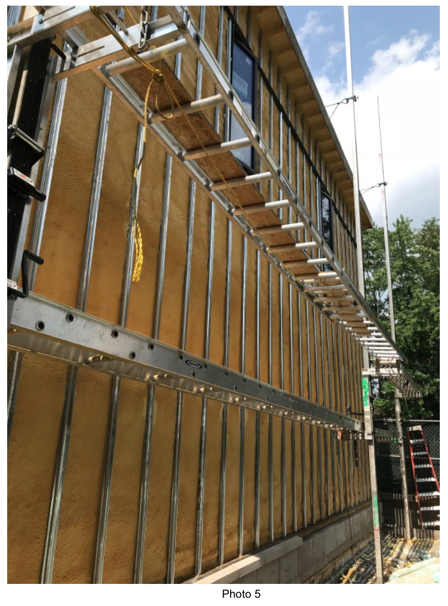
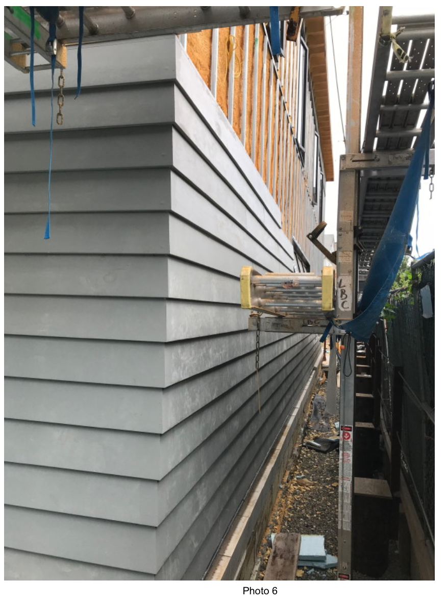
EXO-TEC’s Solution for Attaching Sheathing to the Backup Wall
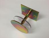
We had to come up with another attachment method for the attachment of the sheathing to the backup wall. I offered the design team my Stand-Off MPV Bracket. They liked it and it was the least costly of the products available on the market in order to meet the code requirement.
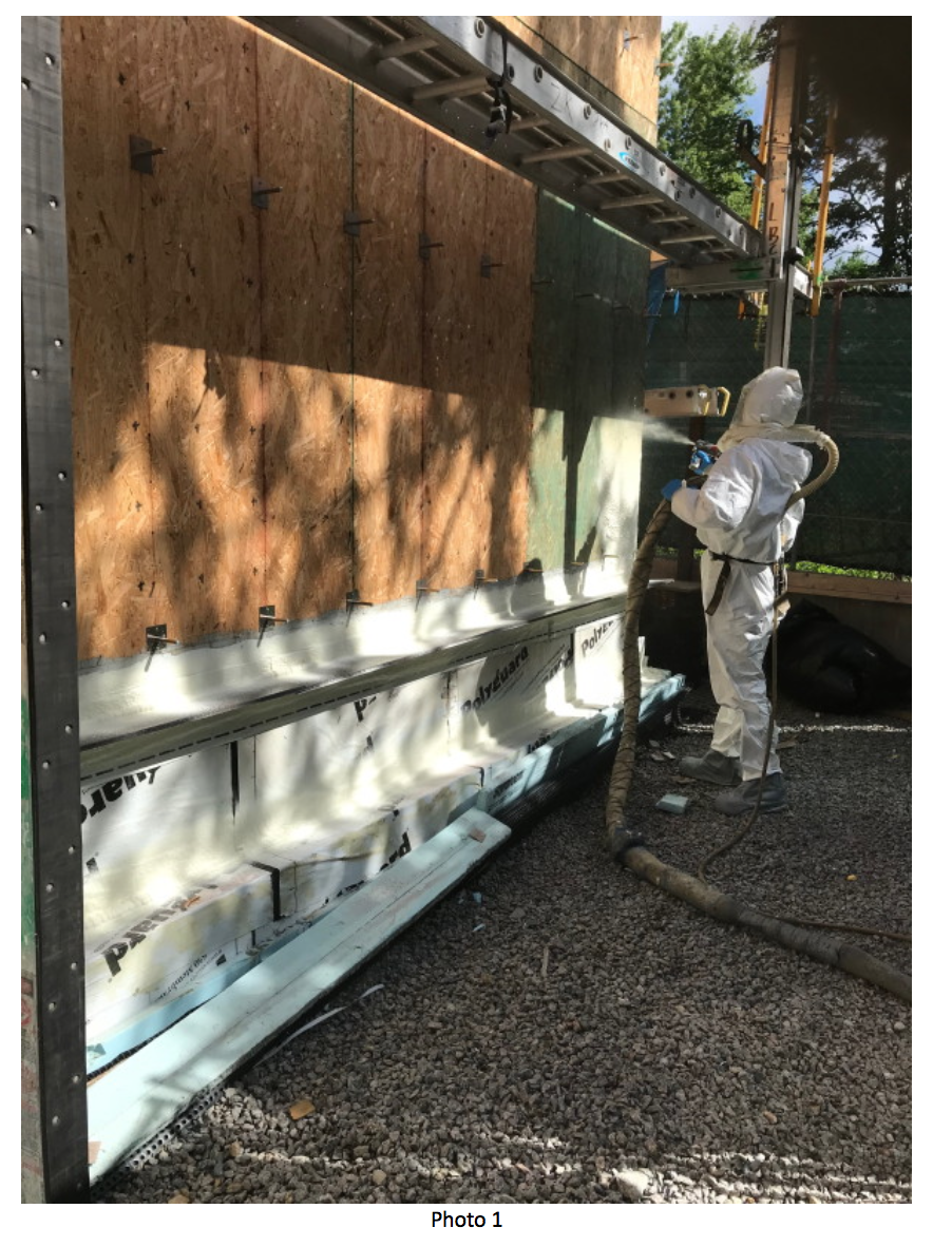
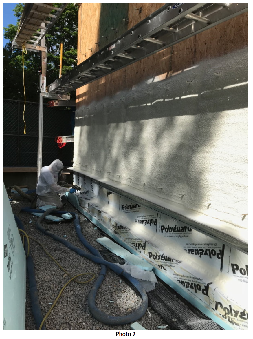
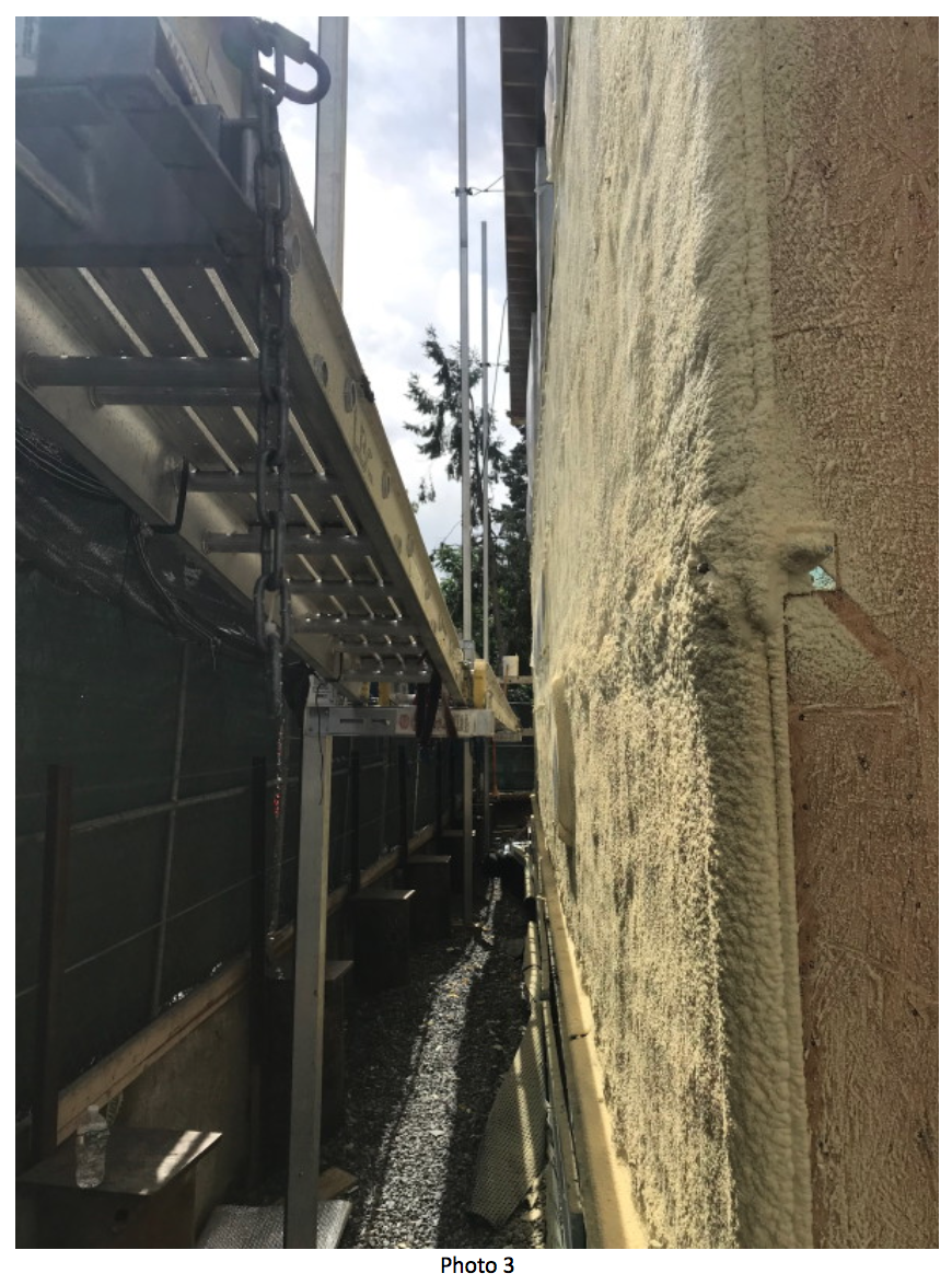
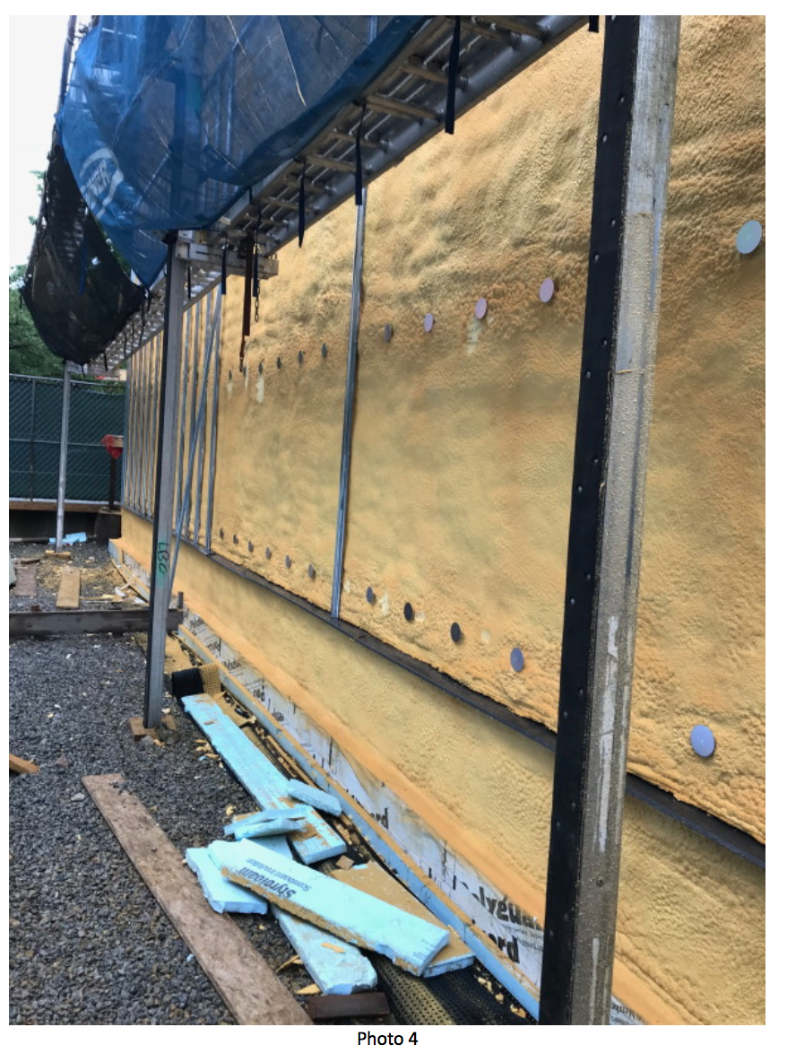
The brackets are spaced at 16” O.C. horizontally and 48” vertically and continuous vertical hat furring members are attached to the top plates of the brackets
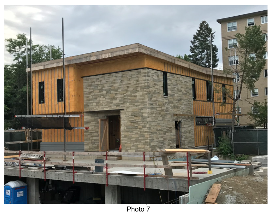
Photos 1 through 7 below show the progression of the work to date.
 Len Anastasi has been working in the construction industry for over 30 years in masonry, waterproofing and restoration work.
He currently owns EXO-TEC Manufacturing, Inc., EXO-TEC Solutions, Inc. and EXO-TEC Consulting, Inc.
In his construction and consulting work, he has performed inspections and repairs on over 300 buildings.
Len has given expert testimony in trials and reviews on dozens of legal cases.
He is a member of ASTM’s E 06 Committee, the Boston Society of Architects Building Enclosure Council, Air Barrier Association of America, the Construction Specifications Institute, and the International Concrete Repair Institute.
Book Len for your Next Event!
Len Anastasi has been working in the construction industry for over 30 years in masonry, waterproofing and restoration work.
He currently owns EXO-TEC Manufacturing, Inc., EXO-TEC Solutions, Inc. and EXO-TEC Consulting, Inc.
In his construction and consulting work, he has performed inspections and repairs on over 300 buildings.
Len has given expert testimony in trials and reviews on dozens of legal cases.
He is a member of ASTM’s E 06 Committee, the Boston Society of Architects Building Enclosure Council, Air Barrier Association of America, the Construction Specifications Institute, and the International Concrete Repair Institute.
Book Len for your Next Event! 
Wow, Len! Thanks for sharing this case history.
Gene
Thanks Len, great article and photo’s to help educate on MVP use. And now I know what a Mikvah is! Vickie